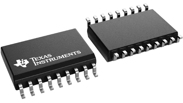
Recently, many friends want to know about the electronic component ULN2803ADWR. As a lover of electronic components, we are happy to share the relevant knowledge of electronic components with you.
Let’s introduce the relevant parameters, performance, advantages and application scope of ULN2803ADWR electronic components.
ULN2803ADWR Overview
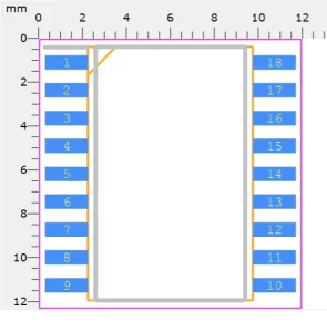
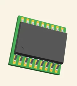
ULN2803ADWR is a high-voltage, high-current relay/inductor driver chip produced by Texas Instruments, which has similar functions to ULN2803A. The ULN2803ADWR comes in a SOIC-18 package, where SOIC stands for Surface Mount Small Outline Integrated Circuit, and the digital package size is 18 pins.
It is designed to control high voltage and high current loads such as relays, stepper motors and LEDs.
How it works
The ULN2803ADWR consists of 8 NPN Darlington pairs that provide the proper current amplification required by the load. We all know that transistors are used to amplify current, but here, Darlington transistor pairs are used inside ICs to do the required amplification.
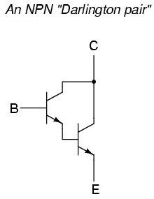
Darlington Pair
A Darlington pair is two transistors that act as a single transistor, providing high current gain. In the pair, the current amplified by the first transistor is further amplified by the next transistor, thus providing a high current to the output terminal.
When no base voltage is applied, when there is no signal at the input pin of the IC, there will be no base current and the transistor remains off. When logic high is fed into the input, both transistors start to conduct, providing a path to ground for the external load connected to the output. Therefore, when an input is applied, the corresponding output pin drops to zero by causing the connected load to complete its path.
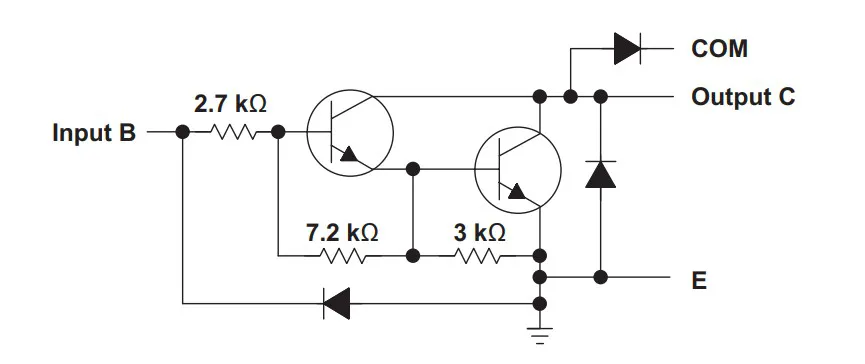
Functional Block Diagram
ULN2803ADWR Features
Supply voltage (VCC): 5V to 50V (reversible) Output current: 500mA (per channel) Collector saturation voltage: 1.1V (maximum) Input voltage range: 0V to 5V Input current: ±0.5mA (high level or low level) Input resistance: 2.4kΩ (typ.) Output type: open drain output (collector) Number of pins: 18 Package Type: SOIC (Small Outline Integrated Circuit Surface Mount) Operating temperature range: -40°C to +85°C
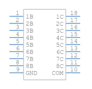
ULN2803ADWR Preview
ULN2803ADWR Advantages
First of all, the ULN2803ADWR chip exhibits excellent reliability and stability. It uses high-quality semiconductor materials and manufacturing processes to ensure its stable operation in various harsh environments. In addition, the ULN2803ADWR chip has the characteristics of low power consumption and high efficiency. Its Darlington structure enables it to deliver high current output while consuming less power, helping to save energy and reduce utility bills. Finally, the ULN2803ADWR chip has a wide range of adaptability and scalability. Its pinout is clearly laid out for easy soldering and installation. At the same time, it is highly integrated and reliable, and it is convenient to connect and expand with other circuit boards or chips. This makes it a flexible and reliable solution for a wide variety of application scenarios.
ULN2803ADWR Application and Implementation
The ULN2803ADWR chip has high voltage, high current drive capability and reliability, and is suitable for multiple application scenarios such as relay driver, stepper motor controler, LED driver, and sensor driver.
Relay driver
ULN2803ADWR can be used to control and drive high voltage and high current relays. It can provide a stable current output, enabling the relay to switch and control various electrical equipment reliably. First, connect the relay to be driven to the output pin of the ULN2803ADWR chip. Each output pin corresponds to a channel and can drive a relay. Connect a suitable power supply to the power pins of the ULN2803ADWR chip. Generally, the power supply voltage should meet the requirements of the relay, and the VCC pin of the chip also needs to be connected to the power supply. Connect the signal source that will control the relay to the input pin of the ULN2803ADWR chip. The input pins can accept low-level or high-level signals for controlling the corresponding output channel. If the driven relay has an inductive load, it is recommended to add a protection diode between the power supply pin of the relay and the load of the relay. Each output channel of the ULN2803ADWR has protection diodes for protection against reverse voltage. By controlling the high and low levels of the input signal, the switch state of the corresponding channel can be controlled.
Stepper Motor Controler
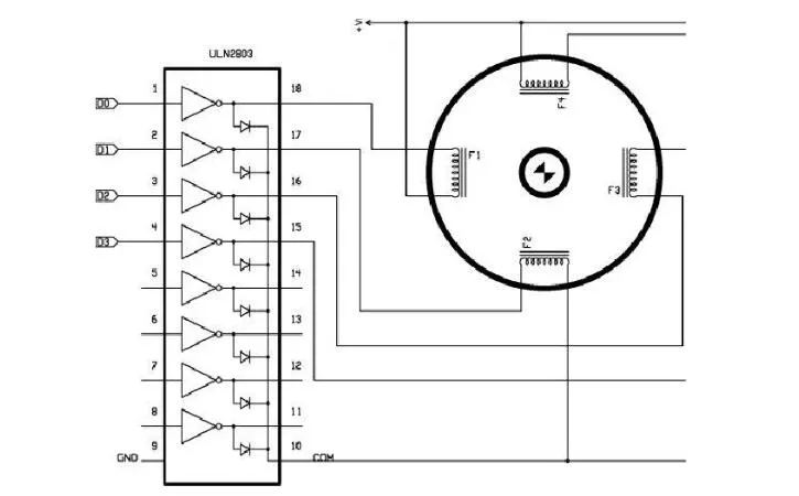
Because of its high current output capability, the ULN2803ADWR is often used to control stepper motors. It can provide enough current to drive each phase of the stepper motor to achieve precise stepping motion. First, connect each phase pin of the stepper motor to the corresponding output pin of the ULN2803ADWR chip. Usually, stepper motors have multiple phases (eg 4 or 8 phases) and each phase needs to be connected with an output pin. Next, connect an appropriate power supply to the power pin of the ULN2803ADWR chip. The power supply voltage should meet the requirements of the stepper motor, and ensure that the VCC pin of the ULN2803ADWR chip is connected to the power supply. Connect the signal source controlling the stepper motor to the input pin of the ULN2803ADWR chip. The control signal can be a level signal (high level or low level) for driving the corresponding output channel. Through appropriate control signals, the rotation direction and step mode (such as full step or half step) of the stepper motor can be controlled. If the stepper motor has an inductive load, it is recommended to add a protection diode between the supply pin and the load. Each output channel of ULN2803ADWR has a protection diode to prevent the influence of reverse voltage. By controlling the high and low levels of the input signal, the switch state of the corresponding channel can be controlled. According to the requirements of the stepper motor, each phase of the stepper motor is driven according to the correct timing and pulse signal.
LED Driver

ULN2803ADWR chip can be used to control and drive LED lights. It can provide enough current to light and control multiple LEDs and is widely used in display screens, indicator lights and lighting systems. First, connect the LED light to be controlled and driven to the output pin of the ULN2803ADWR chip. Each channel corresponds to an output pin to drive an LED light. Next, connect an appropriate power supply to the power pin of the ULN2803ADWR chip. The power supply voltage should match the working voltage requirements of the LED lamp, and at the same time, ensure that the VCC pin of the ULN2803ADWR chip is connected to the power supply. Connect the control signal source to the input pin of the ULN2803ADWR chip. The input signal can be a logic high level or a logic low level, which is used to control the corresponding output channel to realize the switch state control of the LED lamp. If the connected LED lamp needs a current-limiting resistor to ensure normal operation, the current-limiting resistor can be connected between the output pin of the ULN2803ADWR chip and the LED lamp. The value of the current limiting resistor should be calculated according to the characteristics of the LED and the required current. By controlling the high and low levels of the input signal, the switch state of the corresponding channel can be controlled. When the input signal is at a high level, the output pin of the corresponding channel will be at a low level state, thereby turning on the LED light. When the input signal is low, the output pin will be in a high-impedance state, making the LED light off.
Sensor Driver
The ULN2803ADWR chip can also be used to drive various types of sensors, such as photoresistors, temperature sensors, etc. It provides a stable current output for precise control and reading of the sensor. First, connect the inductor to be driven to the output pin of the ULN2803ADWR chip. Each channel corresponds to an output pin to drive an inductor. Next, connect an appropriate power supply to the power pin of the ULN2803ADWR chip. The power supply voltage should match the working voltage requirements of the inductor, and at the same time, ensure that the VCC pin of the ULN2803ADWR chip is connected to the power supply. Connect the control signal source to the input pin of the ULN2803ADWR chip. The input signal can be a logic high level or a logic low level, and is used to control the corresponding output channel, thereby controlling the switching state of the sensor. If the connected inductor has an inductive load, it is recommended to add a protection diode between the supply pin and the load. Each output channel of the ULN2803ADWR has protection diodes for protection against reverse voltage. By controlling the high and low levels of the input signal, the switch state of the corresponding channel can be controlled. When the input signal is at a high level, the output pin of the corresponding channel will be at a low level, thereby driving the sensor to work. When the input signal is low, the output pin will be in a high-impedance state and the sensor will be in an off state.
Finally
Well, the above is our introduction to the ULN2803ADWR chip. If you need to purchase the ULN2803ADWR chip, you can contact us at any time. If you have any questions about the ULN2803ADWR chip, you can also contact us, and we will do our best to answer your questions.

