CRCW040210K0FKED resistor is a common chip resistor, which has the advantages of high precision, small temperature coefficient and good stability. In this tutorial, we will introduce how to use CRCW040210K0FKED resistors to make LED circuits, and help readers understand the basic principles of resistors and their functions in circuits.
Features of CRCW040210K0FKED
CRCW040210K0FKED is a thick film surface mount resistor. Thick film resistors are made by printing a metal conductive film on a ceramic substrate and sintering at high temperature. Its resistance value has nothing to do with the thickness of the glaze, but is determined by the length and width of the conductive film. The metal material of the conductive film is deposited on the ceramic substrate by vacuum sputtering or electrodeposition. During the sintering process, the metal component is completely melted and penetrates into the crystal lattice of the ceramic substrate to form a good ohmic contact.
As a very reliable and stable resistor, CRCW040210K0FKED lasts for 1000 hours at +70°C and still has excellent stability of Δr/r≤1%. Additionally, it features pure tin solder contacts for lead-free environments and compliance with the Restriction of Hazardous Substances (RoHS) directive.
Its main specifications are as follows:
- Resistance value: 10kΩ.
- Tolerance: ±1%.
- Power: 0.063W, 1/16W.
- Dimensions: 0.039"L x 0.020"W (1.00mm x 0.50mm).
- Height - Installed (Max): 0.016" (0.40mm).
- Number of terminals: 2.
- Working temperature: -55°C ~ 155°C.
- Package/Case: 0402 (1005 Metric).
- Vendor Device Package: 402.
- Grade: AEC-Q200.
Light Emitting Diode (LED) Circuits
LEDs (Light Emitting Diodes) emit light when electricity passes through them. The simplest circuit to power an LED is a voltage source with a resistor in series with the LED. Such resistors are often called ballast resistors. Ballast resistors are used to limit the current through the LEDs and prevent excessive current from burning out the LEDs. If the voltage source is equal to the voltage drop across the LED, no resistor is needed. LEDs are also available in integrated packages with the correct resistors for LED operation.
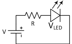
The resistance of a ballast resistor can be easily calculated using Ohm's law and Kirchhoff's circuit laws. Subtract the rated LED voltage from the voltage source and divide by the required LED operating current:
The resistance of the ballast resistor is easy to calculate using Ohm’s law and Kirchhoff’s circuit laws. The rated LED voltage is subtracted from the voltage source, and then divided by the desired LED operating current:

Where V is the voltage source, VLED is the LED voltage, and I is the LED current. This way you can find the right resistor for proper LED operation.
This simple LED circuit with a ballast resistor is often used as a power indicator on a DVD player or computer monitor. Although this circuit is widely used in consumer electronics, it is not energy efficient because the remaining energy of the voltage source is dissipated by the ballast resistor. Therefore, in order to provide better energy efficiency, more complex circuit designs are usually used.
Multiple LEDs in a Series Circuit
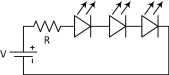
Typically, multiple LEDs of the same type are connected in series to a single voltage source. This way, multiple LEDs can share the same current. It is important to note that the power required to light one LED is the same as the power required to light multiple LEDs in series. To provide sufficient voltage to the LED and resistor in the circuit, the voltage source must be 50% higher than the total voltage drop across the LED and resistor.
Another approach is to use a lower voltage source and current to compensate for the lower brightness of each individual LED by using a higher number of LEDs. This way, due to the lower load, there is less heat loss and the life of the LED will be longer.
Multiple LEDs in a Parallel Circuit
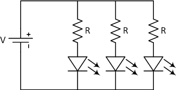
LEDs can be connected in parallel, but this connection can cause more problems than a series circuit. The forward voltages of the LEDs must be very close, otherwise only the LED with the lowest voltage will light and it may be damaged by too much current. Even if LEDs have the same specifications, their current-voltage (I-V) characteristics can be poorly matched due to differences in production processes. This can cause different currents to pass through the LEDs. To minimize current differences, a ballast resistor is usually added to each paralleled LED branch.
Note - How Does the LED Work?
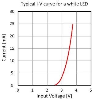
An LED (Light Emitting Diode) is a semiconductor device that essentially consists of a P-N junction with leads on each side. In ideal conditions, the LED has zero resistance in the forward bias and infinite resistance in the reverse bias. However, in practical diodes, a small voltage is needed for conduction, and this voltage along with other characteristics is determined by the diode's materials and structure.
When the forward bias voltage reaches a certain threshold, excess electrons on one side of the P-N junction combine with holes on the other side, releasing energy. Electrons transition to lower energy levels, and this energy is emitted in the form of photons. The emitted light's color is determined by the manufacturing materials, with different materials corresponding to different wavelengths. The first LEDs were made from gallium arsenide, emitting red light, but nowadays LEDs can be made from various materials, enabling emission of a wide range of colors. The operating voltage of LEDs ranges from around 1.6V for red LEDs to approximately 4.4V for ultraviolet LEDs. Understanding the correct operating voltage is crucial, as applying excessive voltage can result in currents beyond the LED's safe handling capacity.
Modern LEDs come in two types: low-power and high-power. Compared to incandescent bulbs of equivalent brightness, LEDs generate less heat, consume less power, and have longer lifespans. LEDs are extensively used in lighting and light sensing applications.
Conclusion
Using CRCW040210K0FKED resistors to make LED circuits is a simple and practical electronic production. Through the introduction of this article, I hope you can master the basic principle of CRCW040210K0FKED resistor and its function in the circuit, and improve your electronic production ability.
If you are interested in CRCW040210K0FKED, or have product requirements for other electronic components, please feel free to contact us.

